

Service Hotline
News
News
Differences Between Y-Type and U-Type Female Header Connectors and Their Applications
2025-12-25
42
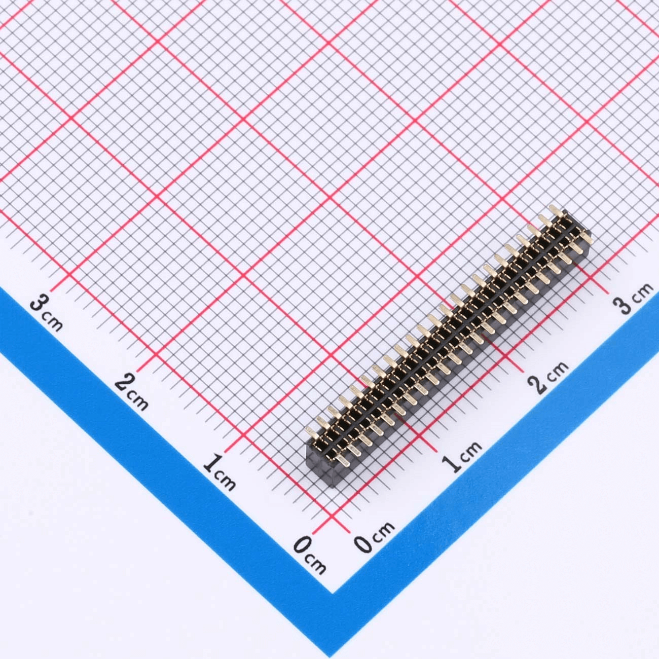
I. Basic Overview of Female Header Connectors
Female header connectors are among the most commonly used interconnection components in the electronics industry. They are primarily used to connect multiple signal lines or power lines between printed circuit boards (PCBs), devices, or systems. Female headers are available in various shapes and structural designs, among which Y-type and U-type are the two most common configurations. Understanding the differences between these two types helps engineers and designers make more appropriate choices for different application scenarios.
II. Features and Applications of Y-Type Female Header Connectors
1. Structural Design of Y-Type Connectors
A Y-type connector typically features three terminals: one input port and two output ports. Its shape resembles the letter “Y,” allowing a signal or power source to be distributed in two directions simultaneously. This design is especially suitable for applications requiring multiple connection points. Internally, Y-type connectors are composed of metal contacts and insulated plastic housings, ensuring reliable electrical contact and long-term durability.
2. Application Scenarios of Y-Type Connectors
Y-type connectors are commonly used in signal distribution and parallel connection applications, particularly where a single signal or power source needs to be shared by multiple devices. For example, in audio equipment, Y-type connectors are often used to split an audio signal from one input into multiple outputs. In power distribution systems, they can also be used to route power from one source to multiple circuits.
3. Advantages and Disadvantages of Y-Type Connectors
Advantages:
Simplified wiring: A single Y-type connector can distribute signals or power to multiple ports, reducing wiring complexity.
Easy maintenance: In the event of a fault, troubleshooting and replacement can be performed quickly.
Compact design: Compared with using multiple separate connectors, Y-type connectors save space and improve layout efficiency.
Disadvantages:
Risk of poor contact: Due to signal or power splitting, there may be a higher risk of contact resistance or uneven current distribution.
Load limitations: In high-power applications, Y-type connectors may not meet current-carrying requirements, limiting their use in certain scenarios.
III. Features and Applications of U-Type Female Header Connectors
1. Structural Design of U-Type Connectors
U-type connectors have a shape similar to the letter “U” and typically feature two terminals: one input and one output. Their design is relatively simple and is mainly intended for direct signal transmission or power connection. Unlike Y-type connectors, U-type connectors do not support signal or power splitting; they function solely as point-to-point connectors.
2. Application Scenarios of U-Type Connectors
U-type connectors are widely used in PCB interconnections and signal transmission applications. In many basic electronic devices, they serve as connectors for power or signal lines. U-type connectors are commonly found in household appliances, automotive electronics, computer hardware, and other industries where stable and straightforward connections are required.
3. Advantages and Disadvantages of U-Type Connectors
Advantages:
Simple structure: The straightforward design results in lower manufacturing costs and wide adoption in low- to medium-power devices.
Easy installation: U-type connectors are easy to assemble and suitable for most standard connection requirements.
Disadvantages:
Limited connectivity: U-type connectors only support one-to-one connections and cannot meet multi-channel signal or power distribution needs.
Limited power handling: Compared with Y-type connectors, U-type connectors generally have lower load capacity and are not suitable for high-power or high-frequency applications.
IV. Comparison Between Y-Type and U-Type Female Header Connectors
| Feature | Y-Type Connector | U-Type Connector |
|---|---|---|
| External Design | Y-shaped, three ports | U-shaped, two ports |
| Application Scope | Signal and power distribution | Simple power or signal connection |
| Function | Supports distribution of multiple signals or power | Primarily used for point-to-point connections |
| Advantages | Saves space, simplifies wiring, suits multiple connections | Simple design, cost-effective, suitable for standard connections |
| Disadvantages | Risk of poor contact, uneven current distribution | Cannot support multi-path connections, not suitable for high-power applications |
V. How to Choose Between Y-Type and U-Type Connectors
The choice between Y-type and U-type connectors mainly depends on your specific application requirements. If you need to distribute a single signal or power source to multiple endpoints and can tolerate certain load limitations, a Y-type connector is likely the better option. On the other hand, if your application only requires a simple point-to-point connection for power or signal transmission, a U-type connector offers a more cost-effective and convenient solution.
VI. Conclusion
Both Y-type and U-type female header connectors have their own distinct advantages and application scenarios. A clear understanding of their structural differences and performance characteristics can help you make more informed decisions during design and component selection. Choosing the right connector not only enhances device performance but also reduces maintenance costs and improves overall system reliability. We hope this article provides useful guidance for your connector selection process.
Related Recommendations